In post 10 of our CO2 as a Refrigerant blog series, I examine the most common and widely adopted CO2 commercial refrigeration system: CO2 booster.
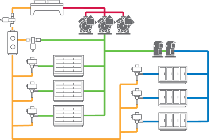
Because of R-744’s high discharge temperature and high differential pressures, a two-stage compression strategy is needed for supercritical low-temperature (LT) applications. Figure 1 depicts a typical architecture of a two-stage CO2 booster system.


Figure 1: Basic architecture of a CO2 booster system
CO2 booster systems are designed so that medium-temperature (MT) compressors discharge into a gas cooler typically located on the roof of a facility. On warm summer days when system pressures could potentially reach 1,400 psig (96.5 bar), R-744 must be cooled and/or condensed — depending on the ambient temperature — before exiting the gas cooler. Refrigerant exiting the gas cooler is circulated back into a facility through a high-pressure valve (HPV), which drops the pressure to a useable state (550 psig [37.9 bar]) and deposits a refrigerant mixture of vapor and liquid inside an insulated receiver (i.e., flash tank) at 40 °F (4 °C) equivalent saturation. Note: 100 percent of a system’s mass flow must pass through the HPV, making it a critical component.
Next, the system circulates the 40 °F (4 °C) liquid through insulated liquid lines to feed all the MT and LT cases and manage the cooling loads. MT cases are equipped with an electronic expansion valve (EEV), and the MT suction gas flows to the MT compressors. On the LT side, where loads could be -20 °F (-29 °C), the cases are also fitted with an EEV and supported by a separate set of LT compressors that discharge into the MT suction group.
The system additionally utilizes a bypass gas valve (BGV) that’s designed and controlled to lower or relieve the pressure on the flash tank. As ambient temperatures rise and fall, flash tank pressures can also fluctuate. The bypass line helps to release the excess flash tank pressure through a bypass gas valve (BGV) and stabilize its setpoint of 550 psig (37.9 bar). The mass flow exiting the BGV is directed into the MT suction group.
In effect, the MT compressors are being fed by three sources:
- The total mass flow and heat of rejection from the LT compressors
- The mass flow from MT suction evaporators
- The mass flow from excess flash gas via the bypass line
The architecture is called a booster system because the LT compressors are not going directly to the gas cooler, as they would on a typical HFC system. Instead, they discharge into the MT compressors, thereby allowing the MT compressors to boost refrigerant to the gas cooler.
In recent years, manufacturers have developed design optimization strategies to maximize CO2 system efficiencies in a variety of different climate conditions. Although stakeholders should evaluate each CO2 system installation with the goals of meeting their own sustainability and operational preferences, the following conclusions may serve as general guidance:
- On an annualized basis, an adiabatic (wet) gas cooler design is most effective in hot, dry climates.
- On an annualized basis, parallel compression is most effective in hot, high-humidity climates.
- Dry gas coolers with parallel compression have provided higher annual energy savings than adiabatic gas coolers in regions where humidity is above 30 percent.
- On the hottest days of a year, adiabatic gas coolers outperform dry gas coolers with parallel compression regardless of climate zone — helping to mitigate peak demand energy charges.
In the next article of this CO2 as a Refrigerant series, I’ll take a closer look at CO2 cascade systems.

Refrigerant Transition Highlights the Importance of Leak Detection
Although detecting and minimizing leaks in commercial refrigeration equipment have always been...

Let the Refrigerant Phase-in Begin
Evaluating next-generation commercial refrigerant alternatives in established and emerging...

Reviewing Proposed Energy Efficiency Standards for Ice Machines
Earlier this year, the Department of Energy (DOE) published a notice of proposed rulemaking (NOPR)...
